

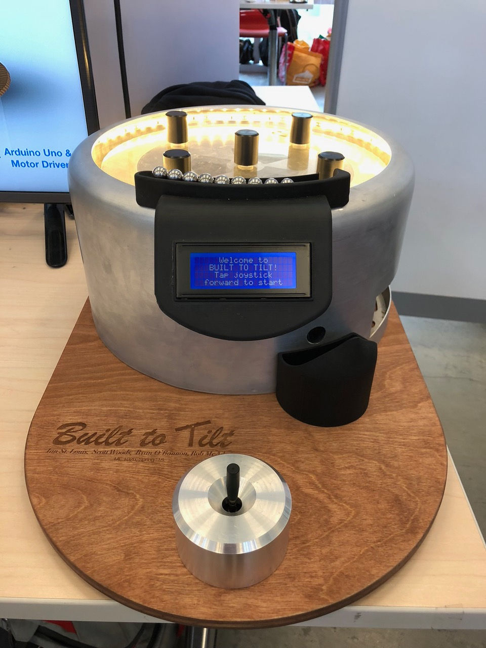
Built to Tilt is an arcade game in which the user can tilt a game board via a joystick in order to guide a ball into a hole. Each time the user successfully rides through the hole of glory, the round increments and the game board begins to spin. The higher the round the harder it gets. How far will you make it?
DESIGN
Initial Concepts: Once our team decided on the game functions, we began to draw up its structure think about how it would need to be built so that the game board could tilt and spin simultaneously. We quickly chose actuators and chose locations for them in the assembly. We developed an enclosure, base, game board, joystick housing, gutter system for collecting and returning balls, and a ball dispensing mechanism.


Component Design: Much love and care went into the design of the components which were visible to the user. In particular, the metal enclosure, joystick housing, base board, display mount, and game board were designed and manufactured with intense effort to be as aesthetic as possible. Functional components like brackets, adapter plates, and the gutter piece were designed for ease of manufacturing. All components involved help from the mechanical engineering student machine shop staff at UC Berkeley.


Enclosure: What started as a pasta pot was machined and joined to other components to form a critical assembly. A special thanks to Jacob Gallego for machining the pot, and to Micheal Nuefer and Daniel Paragas for welding it.


Base: Starting with a piece of scrap plywood, our team laser cut and engraved the base, since its design was planar and all holes were clearance holes. We followed up this process with sanding and stain to give it a very warm and classic appeal and eradicating all signs that it was laser-cut.


Display and Joystick Housings: Our team made use of the Carbon 3D printer at Jacobs hall to print the display mount. We would like to thank Chris Parsell for all his help with the concerted design and fulfillment of these prints. The joystick housing was CNC machined from aluminum.


Game Board: The game board consists of an acrylic plate with Delrin pegs pressed in. The acrylic sheet was laser cut and then sanded to instill opacity that would diffuse light from below and hide electronics on the game board.
The pegs were turned down to create a light press fit into the game board.


Functional Components: The majority of our functional components were designed from aluminum for strength and manufactured via the abrasive water jet in the machine shop. The gutter was printed on the MarkForged 3D printer as three separate pieces designed to snap together. We would like to thank Brien Angelo for his help with cutting and bending sheet metal components, as well as printing the gutter pieces.
ANALYSIS
Mechanism Design Validation: The tilt is actuated by a servo and through a four bar mechanism. The output link of the mechanism is the game board itself, and the input link is the crank of the servo. As the designers of the mechanism, we must understand the relationship between the input and the output. In other words, we need to know what servo crank positions we program in software will correspond to what game board angles. We solve this analytic problem with the assumption that we are in the same angle region (less than 30 degrees of the servo crank). This assumption combined with our knowledge of all the link lengths allows for the analytical solution of the board angle being one half of the servo angle. It is a wonderful and quite useful, linear relationship. In order to validate the analytical solution, we simulated the mechanism in SolidWorks and created a plot of the relationship between input and output. As shown below, the relationship is linear with slope of one half for small angles, which validates our solution.
Note that this mechanism is implemented on both axes, allowing for 3D titling actuation. We avoid locking by using 3D ball joints rather than 2D pin joints.


THE PROTOTYPE


VIDEO DEMOS

All Videos
ELECTRONICS
Actuators: We chose the actuators for our design early on, so that we could rapidly integrate them into the mechanical system. We chose to use servos for the tilting actuation because of their precise position, controllability and high torque to volume ratio. We chose a compact DC gear motor for the spin actuation because of its simplicity, high torque to volume ratio, and ability to spin continuously.


Sensors, Radios, and Controllers: The electronics attached to the base are controlled via an Arduino Uno microprocessor. Because the game board spins continuously, and the electronics on the base are stationary, the electronics on the game board are controlled by a separate Arduino Nano. In order to track the progress and score of the game, we used a radio transmitter, receiver, and three IR sensors. One sensor is placed at the scoring hole on the game board and the other two at the outlet of the gutter (on the stationary base) which the scoring hole feeds to. When a ball is scored, the IR sensor on the game board measures multiple consecutive low-voltage readings and the radio transmitter increments its internal score count. Once the ball travels down the gutter to the exit of the enclosure, one of two IR sensors spots it and has the radio receiver check for a goal scored with the transmitter's broadcast. If the Tx module has not incremented its score, the user loses a life. Otherwise, the score and round increments on the Uno and a new round begins!


User Interface: The user interacts with the game through the joystick and the LCD Screen. He or she can start a new game as well as control the tilt of the game board using the joystick. He or she can read the score of the game, instructions on how to play, and words of encouragement from the LCD display.


User Experience: Our main goal for this project was to make a sleek and unmistakably beautiful arcade-style game to bring people back to the games of their childhood. We wanted to make every part of the project picture-perfect, and our attention to detail can be seen in the cleanliness of the code, the immaculate electronics placement and wiring, and the finish on each of our user-facing components.
Further, we designed the game to be simple enough that the learning curve is not steep, but difficult enough that the game is immensely addicting. You feel like the power is always in your hands, and can recalibrate your play-style after each life lost to get even further in the game the next time. This is the most addicting feature. We also paid very close attention to low-latency actuation so the user feels as though the joystick is truly an extension of their body.
SOFTWARE
The code running on the Arduino Uno controls the heart of the system. This code monitors gameplay, lives left and the current round; reads user input; sends commands to all four motors; and receives communication from the Nano regarding points scored. Three variables are responsible for controlling gameplay: lives, currentRound, and gameStatus. Upon startup, these variables default to 3, 1, and 0 respectively.
The Uno runs through one of two loops, depending on whether a game is in progress as indicated by gameStatus. If there is no game, the Uno runs once through a loop that requests user input to start a game on the LCD, flashes instructions, then begins the game. The game begins when gameStatus is set to 1 and a ball is dropped from the dispenser.
Once a game is in progress, the Uno runs through a different loop. In each iteration of this loop, external functions are called that read the joystick potentiometers and set the servo position, set the DC motor speed based on the round number and preset timing, and check the gutter IR sensors for the presence of a ball. If a ball is detected in the gutter, then the code checks the radio receiver to see if the ball was scored, or fell into the gutter. The newly received integer is compared to the number received last time a ball was detected. If they are the same, the ball fell into the gutter; if they differ, then the ball was scored and triggered the IR sensor on the game board. The lives left variable is adjusted accordingly, and if the user has lives left, the LCD is updated with new round information and a new ball is released, starting the loop over.
The Arduino Nano is critical for detecting scores, but acts as a dumb transmitter. Once the Nano is powered, it runs a similar procedure to establish a nominal sensor value. During its loop, it constantly checks for dips in the sensor output below a threshold, and broadcasts an integer corresponding to the number of scores it has detected since startup. If a new score is detected, the Nano increments the number it broadcasts by 1, then resumes its loop.
After the end of each round, a message is displayed to the user, corresponding to whether they scored or not. The messages are chosen randomly from preset lists to add variety and interest at the end of each round.
Game Code Files


MEET OUR TEAM

Ian St. Louis
ianstlouis.com
Ian is a senior mechanical engineer interested in product design for consumer electronics. He spent 7 months on the Display Engineering team at Apple during his third year at Cal and will continue with them after graduation. In the Fall of 2019, Ian plans on pursuing is M.S. in Mechanical Engineering at UC Berkeley.

Ryan O'Bannon
Ryan is a senior mechanical engineer interested in product design and mechatronics. Last summer he interned with the Hardware Reliability Team at Apple. After graduation he will be working as a product design engineer in the Consumer Hardware Division at Google.

Rob McAdam
Rob is a senior mechanical engineer interested in product design. He spent 12 months in SPG Product Design at Apple, forgoing his junior year at Cal. Rob is returning to the same role full time after graduation this spring.

Scott Woods
Scott is a senior mechanical engineer with a minor in energy engineering. He spent the last summer at Raytheon as manufacturing engineering intern and is returning for a full time role following graduation.

Final Acknowledgements
Our team would like to thank the UC Berkeley Mechanical Engineering student machine shop and the staff in Hesse for all their invaluable design insight, manufacturing help, and electronics support. This project never could have come to life without all their support and unwavering resolve to see our project come to light.